Monday 30 May 2022

Algorithm for Concave Hull of Polygons

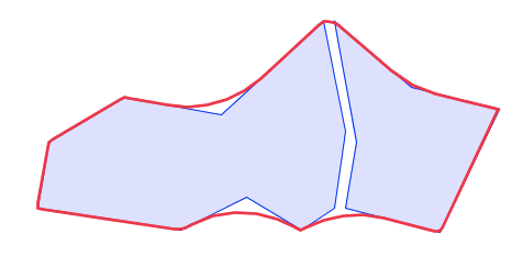
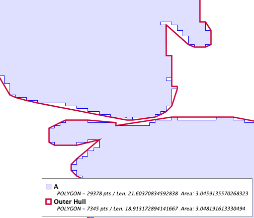
The previous post introduced the new ConcaveHullOfPolygons class in the JTS Topology Suite.  This allows computing a concave hull which is constrained by a set of polygonal geometries.  This supports use cases including:

  • generalization of groups of polygon
  • joining polygons
  • filling gaps between polygons

A concave hull of complex polygons

The algorithm developed for ConcaveHullOfPolygons is a novel one (as far as I know).  It uses several features recently developed for JTS, including a neat trick for constrained triangulation.  This post describes the algorithm in detail.

The construction of a concave hull for a set of polygons uses the same approach as the existing JTS ConcaveHull implementation.  The space to be filled by a concave hull is triangulated with a Delaunay triangulation.  Triangles are then "eroded" from the outside of the triangulation, until a criteria for termination is achieved.  A useful termination criteria is that of maximum outside edge length, specified as either an absolute length or a fraction of the range of edge lengths.

For a concave hull of points, the underlying triangulation is easily obtained via the Delaunay Triangulation of the point set.  However, for a concave hull of polygons the triangulation required is for the space between the constraint polygons.  A simple Delaunay triangulation of the polygon vertices will not suffice, because the triangulation may not respect the edges of the polygons.  

Delaunay Triangulation of polygon vertices crosses polygon edges

What is needed is a Constrained Delaunay Triangulation, with the edge segments of the polygons as constraints (i.e. the polygon edge segments are present as triangle edges, which ensures that other edges in the triangulation do not cross them).  There are several algorithms for Constrained Delaunay Triangulations - but a simpler alternative presented itself.  JTS recently added an algorithm for computing Delaunay Triangulations for polygons.  This algorithm supports triangulating polygons with holes (via hole joining).  So to generate a triangulation of the space between the input polygons, they can be inserted as holes in a larger "frame" polygon.  This can be triangulated, and then the frame triangles removed. Given a sufficiently large frame, this leaves the triangulation of the "fill" space between the polygons, out to their convex hull. 

Triangulation of frame with polygons as holes

The triangulation can then be eroded using similar logic to the non-constrained Concave Hull algorithm.  The implementations all use the JTS Tri data structure, so it is easy and efficient to share the triangulation model between them. 

Triangulation after removing frame and eroding triangles

The triangles that remain after erosion can be combined with the input polygons to provide the result concave hull.  The triangulation and the input polygons form a polygonal coverage, so the union can be computed very efficiently using the JTS CoverageUnion class.  If required, the fill area alone can be returned as a result, simply by omitting the input polygons from the union.

Concave Hull and Concave Fill

A useful option is to compute a "tight" concave hull to the outer boundary of the input polygons.  This is easily accomplished by removing triangles which touch only a single polygon.  

Concave Hull tight to outer edges


Concave Hull of complex polygons, tight to outer edges.

Like the Concave Hull of Points algorithm, holes are easily supported by allowing erosion of interior triangles.

Concave Hull of Polygons, allowing holes

The algorithm performance is determined by the cost of the initial polygon triangulation.  This is quite efficient, so the overall performance is very good.

As mentioned, this seems to be a new approach to this geometric problem.  The only comparable implementation I have found is the ArcGIS tool called Aggregate Polygons, which appears to provide similar functionality (including producing a tight outer boundary).  But of course algorithm details are not published and the code is not available.  It's much better to have an open source implementation, so it can be used in spatial tools like PostGIS, Shapely and QGIS (based on the port to GEOS).  Also, this provides the ability to add options and enhanced functionality for use cases which may emerge once this gets some real-world use.

Friday 20 May 2022

Concave Hulls of Polygons

A common spatial need is to compute a polygon which contains another set of polygons.  There are numerous use cases for this; for example:

  • Generalizing groups of building outlines (questions: 1, 2
  • Creating "district" polygons around block polygons (questions: 1)
  • Removing gaps between sets of polygons (questions: 1, 2, 3, 4)
  • Joining two polygons by filling the space between them (questions: 1, 2)     
This post describes a new approach for solving these problems, via an algorithm for computing a concave hull with polygonal constraints.  The algorithm builds on recent work on polygon triangulation in JTS, and uses a neat trick which I'll describe in a subsequent post.  

Approach: Convex Hull

The simplest way to compute an area enclosing a set of geometries is to compute their convex hull.  But the convex hull is a fairly coarse approximation of the area occupied by the polygons, and in most cases a better representation is required.  

Here's an example of gap removal between two polygons.  Obviously, the convex hull does not provide anything close to the desired result: 

Approach: Buffer and Unbuffer

A popular suggestion is to buffer the polygon set by a distance sufficient to "bridge the gaps", and then "un-buffer" the result inwards by the same (negative) distance.  But the buffer computation can "round off" corners, which usually produces a poor match to the input polygons.  It also fills in the outer boundary of the original polygons.

Approach: Concave Hull of Points

A more sophisticated approach is to use a concave hull algorithm.  But most (or all?) available concave hull algorithms use points as the input constraints. The vertices of the polygons could be used as the constraint points, but since the polygon boundaries are not respected, the computed hull may cross the polygon edges and hence not cover the polygons.  

Densifying the polygon boundaries helps, but introduces another problem - the computed hull can extend beyond the outer boundaries of individual polygons.  And it introduces new vertices not present in the original data.

Solution: Concave Hull of Polygons

What is needed is a concave hull algorithm that accepts polygons as constraints, and thus respects their boundaries.  The JTS Topology Suite now provides this capability in a class called ConcaveHullOfPolygons (not a cute name, but descriptive).  It provides exactly the solution desired for the gap removal example:  

The Concave Hull of Polygons API

Like concave hulls of point sets, concave hulls of polygons form a sequence of hulls, with the amount of concaveness determined by a numeric parameter. ConcaveHullOfPolygons uses the same parameters as the JTS ConcaveHull algorithm.  The control parameter determines the maximum line length in the triangulation underlying the hull.  This can be specified as an absolute length, or as a ratio between the longest and shortest lines.  

Further options are:

  • The computed hull can be kept "tight" to the outer boundaries of the individual polygons.  This allows filling gaps between polygons without distorting their original outer boundaries.  Otherwise, the concaveness of the outer boundary will be decreased to match the distance parameter specified (which may be desirable in some situations).
  • Holes can be allowed to be present in the computed hull
  • Instead of the hull, the fill area between the input polygons can be computed.  
As usual, this code will be ported to GEOS, and from there it can be exposed in the downstream libraries and projects.

Examples of Concave Hulls of Polygons

Here are examples of using ConcaveHullOfPolygons for the use cases above:

Example: Generalizing Building Groups

Using the "tight" option allows following the outer building outlines.


Example: Aggregating Block Polygons

The concave hull of a set of block polygons for an oceanside suburb.  Note how the "tight" option allows the hull to follow the convoluted, fine-grained coastline on the right side.

Example: Removing Gaps to Merge Polygons

Polygons separated by a narrow gap can be merged by computing their concave hull using a small distance and keeping the boundary tight.

Example: Fill Area Between Polygons

The "fill area" portion of the hull between two polygons can be computed as a separate polygon. This could be used to provide an "Extend to Meet" construction by unioning the fill polygon with one of the input polygons.  It can also be used to determine the "visible boundary", provided by the intersection of the fill polygon with the input polygon(s).


Wednesday 4 May 2022

Using Outer Hulls for Smoothing Vectorized Polygons

The electrons were hardly dry on the JTS Outer and Inner Polygon Hull post when another interesting use case popped up on GIS StackExchange.  The question was how to remove aliasing artifacts (AKA "jaggies") from polygons created by vectorizing raster data, with the condition that the result should contain the original polygon.  

A polygon for Vancouver Island vectorized from a coarse raster dataset.  Aliasing artifacts are obvious.

This problem is often handled by applying a simplification or smoothing process to the "jaggy" polygon boundary.  This works, as long as the process preserves polygonal topology (e.g. such as the JTS TopologyPreservingSimplifier). But generally this output of this process does not contain the input polygon, since the simplification/smoothing can alter the boundary inwards as well as outwards.  

Simplification using TopologyPreservingSimplifier with distance = 0.1.  Artifacts are removed, but the simplified polygon does not fully contain the original.

In contrast, the JTS Polygon Outer Hull algorithm is designed to do exactly what is required: it reduces the number of vertices, while guaranteeing that the input polygon is contained in the result.  It is essentially a simplification method which also preserves polygonal topology (using an area-based approach similar to the Visvalingham-Whyatt algorithm).

Outer Hull using vertex ratio = 0.25.  Artifacts are removed, and the original polygon is contained in the hull polygon.

Here's a real-world example, taken from the GADM dataset for administrative areas of Germany.  The coastline of the state of Mecklenburg-Vorpommern appears to have been derived from a raster, and thus exhibits aliasing artifacts.  Computing the outer hull with a fairly conservative parameter eliminates most of the artifacts, and ensures polygonal topology is preserved.

A portion of the coastline of Mecklenburg-Vorpommern showing aliasing artifacts.  The Outer Hull computed with vertex ratio = 0.25 eliminates most artifacts, and preserves the coastline topology.

Future Work

A potential issue for using Outer Hull as a smoothing technique is the choice of parameter value controlling the amount of change.  The algorithm provides two options: the ratio of reduction in the number of vertices, or the fraction of change in area allowed.  Both of these are scale-independent, and reflect natural goals for controlling simplification.  But neither relate directly to the goal of removing "stairstep" artifacts along the boundary.  This might be better specified via a distance-based parameter. The parameter value could then be determined based on the known artifact size (i.e. the resolution of the underlying grid).  Since the algorithm for Outer Hull is quite flexible, this should be feasible to implement.