Wednesday, 23 December 2020

Fixing Buffer for fixing Polygons

The OGC Simple Features specification implemented by JTS has strict rules about what constitutes a valid polygonal geometry.  These include:

  • Polygon rings must be simple; i.e. they may not touch or cross themselves
  • MultiPolygon elements may not overlap or touch at more than a finite number of points (i.e they may not intersect along an edge)
These rules were chosen for good reason. They ensure that OGC-valid polygonal geometry is the simplest possible representation of an enclosed area.  This greatly simplifies the evaluation of most operations on polygonal geometry, which leads to improved performance.  JTS operations generally require input which is valid according to OGC rules.  And they always (with some rare exceptions) emit result geometry which is OGC-valid.

But data in the wild is often not this well-behaved.  This creates the need to "clean" or "make valid"  polygonal geometry in order to carry out operations on it.  Shortly after JTS was first released we discovered a useful trick: constructing a zero-width buffer via geom.buffer(0) converts an invalid polygonal geometry into a valid one.  It can also be used as a simple way of converting "inverted" polygon topology (ESRI-style) into valid OGC topology.  The reason this works is that the buffer algorithm inherently has to handle overlaps and self-intersections since they often occur during the generation of raw buffer offset curves.  The algorithm nodes self-intersections, merges overlaps, and creates new polygons or holes if necessary.

A polygon with many invalidities: overlap, self-touch in point and line, and a "bow-tie".


The polygon fixed by using buffer(0)
Note that the bow-tie portion on the right is considered to lie in the exterior of the polygon due to ring orientation, and thus is removed.

In the 20 years since the release of JTS (and its derivative GEOS) this trick has passed into the lore of open-source spatial data processing. It has become a recommended technique for fixing invalid polygonal geometry in numerous projects, such as PostGISShapelyRGeoGeoToolsR-sf and QGIS. It's also used internally in JTS, in algorithms such as DouglasPeuckerSimplifier, VWSimplifier, and Densifier which might otherwise produce invalid polygonal results.

BUT - there's a nasty little surprise lying in wait for users of buffer(0)! It doesn't always work.  It turns out that the buffer algorithm has a serious flaw: in some situations involving invalid "bow-tie" topology it will discard a large part of the input geometry.  This has been reported in quite a few issues (here and here in JTS, and also in  GEOS and Shapely).   
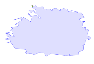
Result of running DouglasPeuckerSimplifier on a polygon with a bow-tie. (See issue)

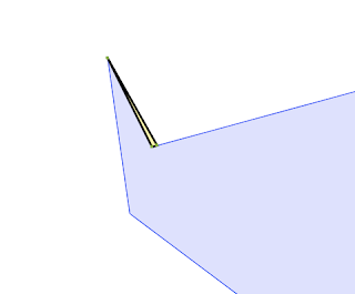
Close-up of the result -  clearly undesirable.

The problem occurs because the buffer algorithm computes the orientation of rings in order to build the buffer offset curve (in the case of a zero-width buffer this is just the original ring linework). Currently the Orientation.isCCW test is used to do this. This uses an efficient algorithm that determines ring orientation by checking the line segments incident on the uppermost vertex of the ring (see Wikipedia for an explanation of why this works.) For a valid ring (where the linework does not cross itself) this works perfectly. However, in a invalid self-crossing ring (sometimes called a "bow-tie" or "figure-8") a choice must be made about which lobe is assigned to be the "interior". The upper-vertex approach always picks the top lobe.  If that happens to be very small, the larger part of the ring is considered "exterior" and hence is removed by buffering.  

A bow-tie polygon where buffer makes the evidently wrong choice for interior.
The problem occurs for non-zero buffer distances as well.

This problem has limped along for many years now, never being quite enough of a pain point to motivate the effort needed to find a fix (or to fund one!).  And to be honest, the buffer code is some of the most complicated and delicate in JTS, and I was concerned about wading into it to add what seemed poised to be a fiddly correction.

But recently there has been renewed interest in providing a Make-Valid capability for JTS.  This inspired me to revisit the usage of buffer(0), and think more deeply about ring orientation and its role in determining valid polygonal topology. And this led to discovering a surprisingly simple solution for the buffer issue.

The fix is to use an orientation test which takes into account the entire ring. This is provided by the Signed-Area Orientation test, implemented in Orientation.isCCWArea using the Shoelace Formula. This effectively determines orientation based on the largest area enclosed by the ring. This corresponds more closely to user expectation based on visual assessment. It also minimizes the change in area and (usually) extent.

And indeed it works:


It fixes the simplification issue nicely:


The fix consists of about 4 lines of actual code.  To paraphrase a great orator, never in the history of JTS has so much benefit been given to so many by so few lines of code.  Now buffer(0) can be recommended unreservedly as an effective, performant way to fix polygonal geometry.  And all those helpful documentation pages can drop any qualifications they might have.

As usual, this fix will soon show up in GEOS, and from there in PostGIS and other downstream projects.  

This isn't the end of the story.  There are times when the effect of buffer(0) is not what is desired for fixing polygon topology.  This is discussed nicely in this blog post.  The ongoing research into Make Valid will explore alternatives and how to provide an API for them.

Friday, 18 December 2020

Randomization to the Rescue!

Now that OverlayNG has landed on JTS master, it is getting attention from downstream projects interested in porting it or using it.  One of the JTS ports is the Net Topology Suite (NTS) project, and it is very proactive about tracking the JTS codebase.  Soon after the OverlayNG commit an NTS developer noticed an issue while running the performance tests in JTS: the InteriorPointInAreaPerfTest was now causing a StackOverflowError.  This turned out to be caused by the change to GeometryPrecisionReducer to use OverlayNG with Snap-Rounding to perform robust precision reduction of polygons.  Further investigation revealed that failure was occurring while querying the KdTree used in the HotPixelIndex in the SnapRoundingNoder.  Moreover, in addition to the outright failure, even when queries did succeed they were taking an excessively long time for large inputs.

The reason for using a K-D tree as the search structure for HotPixels is that it supports two kinds of queries with a single structure: 

  • Lookup queries to find the HotPixel for a coordinate.  These queries are performed while building the index incrementally. Hence a dynamic data structure like a K-D tree is required, rather than a static index such as STRtree.
  • Range queries to find all HotPixels within a given extent.  These queries are run after the index is loaded.

The JTS KdTree supports both of these queries more efficiently than QuadTree, which is the other dynamic index in JTS.  However, K-D trees are somewhat notorious for becoming unbalanced if inserted points are coherent (i.e. contain monotonic runs in either ordinate dimension).  This is exactly the situation which occurs in large, relatively smooth polygons - which is the test data used in InteriorPointInAreaPerfTest.  An unbalanced tree is deeper than it would be if perfectly balanced.  In extreme cases this leads to trees of very large depth relative to their size.  This slows down query performance and, because the KdTree query implementation uses recursion, can also lead to stack overflow.  

A perfectly balanced K-D tree, with depth = logN.  In the worst case an unbalanced tree has only one node at each level (depth = N).

I considered a few alternatives to overcome this major blocker.  One was to use a QuadTree, but as mentioned this would reduce performance.  There are schemes to load a K-D tree in a balanced way, but they seemed complex and potentially non-performant.

It's always great when people who file issues are also able to provide code to fix the problem.  And happily the NTS developer submitted a pull request with a very nice solution.  He observed that while the K-D tree was being built incrementally, in fact the inserted points were all available beforehand.  He proposed randomizing them before insertion, using the elegantly simple Fisher-Yates shuffle.  This worked extremely well, providing a huge performance boost and eliminated the stack overflow error.  Here's the relative performance times:

Num PtsRandomizedIn Order
10K126 ms341 ms
20K172 ms1924 ms
50K417 ms12.3 s
100K1030 ms59 s
200K1729 ms240 s
500K5354 msOverflow

Once the solution was merged into JTS, my colleague Paul Ramsey quickly ported it to GEOS, so that PostGIS and all the other downstream clients of GEOS would not encounter this issue.

It's surprising to me that this performance issue hasn't shown up in the other two JTS uses of KdTree: SnappingNoder and ConstrainedDelaunayTriangulator. More investigation required!


Thursday, 8 October 2020

OverlayNG lands in JTS master

I'm happy to say that OverlayNG has landed on the JTS master branch!  This is the culmination of over a year of work, and even more years of planning and design.  It will appear in the upcoming JTS 1.18 release this fall.

As described in previous posts OverlayNG brings substantial improvements to overlay computation in JTS:  

  • A completely new codebase provides greater clarity, maintainability, and extensibility
  • Pluggable noding supports various kinds of noding strategies including Fast Full-Precision Noding, Snapping and Snap-Rounding.
  • Optimizations are built-in, including new ones such as Ring Clipping and Line Limiting.
  • Additional functionality including Precision Reduction and Fast Coverage Union

All of these improvements are encapsulated in the new OverlayNGRobust class. It provides fully robust execution with excellent performance, via automated fallback through a series of increasingly robust noding strategies.  This should solve a host of overlay issues reported over the years in various downstream projects such as GEOS, PostGIS, Shapely, R-sf and QGIS. (Many of these cases have been captured as  XML tests for overlay robustness, to ensure that they are handled by the new code).

Initially the idea was to use OverlayNG as an opportunity to simplify and improve the semantics of overlay output, including:

  • Sewing linear output node-to-node (to provide a full union)
  • Ensuring output geometry is homogeneous (to allow easy chaining of overlay operations)
  • Omitting lines created by topology collapse in polygonal inputs

In the end we decided that this change would have too much impact on existing tests and downstream code, so the default semantics are the same as the previous overlay implementation.  However, the simplified semantics are available as a "strict" mode for overlay operations.  

At the moment OverlayNG is not wired in to the JTS Geometry overlay operations, but is provided as a separate API.  The plan is to provide a runtime switch to allow choosing which overlay code is used.  This will allow testing in-place while avoiding potential impact on production systems.  GeometryPrecisionReducer has been changed to use OverlayNG with Snap-Rounding, to provide more effective precision reduction.

GEOS has been tracking the OverlayNG codebase closely for a while now, which has been valuable to finalize the overlay semantics, and for finding and fixing issues.  Having the code in JTS master gives the green light for downstream projects to do their own testing as well. There have been a few issues reported:

  • A minor copy-and-paste variable name issue in HotPixel (which did not actually cause any failures, since it was masked by other logic)
  • A clarification about the new behaviour of GeometryPrecisionReducer, revealed by an NTS test
  • Most notably, a serious performance issue with Snap-Rounding of large geometries was identified and fixed by a member of the NTS project.  This is quite interesting, so I'll discuss it in detail in another post.

After years of designing and developing improvements to overlay, it's great to see OverlayNG make its debut.  Hopefully this will be the end of issues involving the dreaded TopologyException. And the new design will make it easier to build other kinds of overlay operations, including things like fast line clipping, split by line, coverage overlay... so stay tuned! 

Saturday, 20 June 2020

JTS OverlayNG - Tolerant Topology Transformation

This is another in a series of posts about the new OverlayNG algorithm being developed for the JTS Topology Suite. (Previous ones are here and here).  Overlay is a core spatial function which allows computing the set-theoretic boolean operations of intersection, union, difference, and symmetric difference over all geometry types. OverlayNG introduces significant improvements in performance, robustness and code design.

JTS has always provided the ability to specify a fixed-precision model for computing geometry constructions (including overlay).  This ensures that output coordinates have a defined, limited precision.  This can reduce the size of data transfers and storage, and generally leads to cleaner, simpler geometric output.  The original overlay implementation had some issues with robustness, which were exacerbated by using fixed-precision.  One of the biggest improvements in OverlayNG is that fixed-precision overlay is now guaranteed to be fully robust.  This is achieved by using an implementation of the well-known snap-rounding noding paradigm. 

Geometric algorithms which operate in a fixed-precision model can encounter situations called topology collapse.  This happens when line segments and points become coincident due to vertices or intersection points being rounded.  The OverlayNG algorithm detects occurrences of topology collapse and transforms them into valid topology in the overlay result.

Topology collapse during overlay with a fixed precision model

As a bonus, handling topology collapse during the overlay process also allows it to be tolerated when present in the original input geometries.  This means that some kinds of "mildly" invalid geometry (according to the OGC model) are acceptable as input.  Invalid geometry is transformed to valid geometry during the overlay process.

Specifically,  input geometry may contain the following situations, which are invalid in the OGC geometry model:
  • A ring which self-touches at discrete points (the so-called "inverted polygon" or "exverted hole")
  • A ring which self-touches in one or more line segments
  • Rings which touch other ones along one or more line segments 
Note that this does not extend to handling polygons that overlap, rather than simply touch.  These are "strongly invalid", and will trigger a TopologyException during overlay.

An interesting use for this capability is to process individual geometries.  By simply computing the union of a single geometry the geometry is transformed into an OGC-valid geometry.  In this way OverlayNG functions as a (partial) "MakeValid" operation.  
A polygon which self-touches in a line transforms to a valid polygon with a hole

A polygon which self-touches in a point transforms to a valid polygon with a hole

A collection of polygons which touch in lines transforms to a valid polygon with a hole

Moreover, some spatial systems use geometry models which do not conform to the OGC semantics.  Some systems (such as ArcGIS) actually specify the use of inverted polygons and exverted holes in their topology model.  And in days of yore there were systems which were unable to model holes explicitly, and so used a "connected hole" topology hack (AKA "lollipop holes".) This represented  holes as an inversion connected by a zero-width corridor to the polygon shell. Both of these models are accepted by OverlayNG. Thus it provides a convenient way to convert from these non-standard models into OGC-valid topology. 

This is one more reason why overlay is the real workhorse of spatial data processing!


Thursday, 18 June 2020

JTS OverlayNG - Noding Strategies

In a previous post I unveiled the exciting new improvement in the JTS Topology Suite called OverlayNG.  This new implementation provides significant improvements to the core function of spatial overlay.  Overlay supports computing the set-theoretic boolean operations of intersection, union, difference, and symmetric difference over all geometric types.

One of the design goals of JTS is to create modular, reusable data structures and processes to implement spatial algorithms.  This increases development velocity and testability, and makes algorithms easier to understand.  In spatial algorithms it is not always obvious how to identify appropriate abstractions for reuse, so this is an on-going effort of design and refactoring.

After the implementation of spatial overlay in the very first release of JTS, it became clear that overlay can be split into the following phases:

  1. Noding, in which an set of possibly-intersecting linestrings is converted to an arrangement in which linestrings touch only at endpoints
  2. Topology Analysis, during which the topology graph of the noded arrangement is determined
  3. Result Extraction, in which the geometric components of the desired result are extracted from the topology graph

It also became clear that the Noding phase is critical, since it determines the overall performance and robustness of the overlay computation.  Moreover, tradeoffs between these two qualities can be made by using different noding strategies.  For instance, the "classic" JTS noding approach is fast, but susceptible to robustness issues.  Alternatively, noding using the well-known snap-rounding paradigm is slower, but can be made fully robust. 

To encapsulate this concept, JTS introduced the Noder API.  Since it post-dated the original overlay code, using it in overlay had to await a reworking of that codebase.  The OverlayNG project provided this opportunity.  OverlayNG allows supplying a specific Noder class to be used during overlay. 

One of the main goals of the OverlayNG project was to develop a noder to provide fully robust noding.  This would eliminate the notorious TopologyException errors which bedevil the use of overlay.  The effort has paid off with the development of not one, but two new noders.  The Snapping Noder has very good performance and (with the addition of some heuristics, and so far as is known) provides robust full-precision evaluation.  And the Snap-Rounding noder provides guaranteed robustness as well the ability to enforce a fixed-precision model for output.

So now OverlayNG can be run with the following suite of noders, depending on use case.  The images show the result of intersection and union on the following geometries:


Fast Full-Precision Noder

The MCIndexNoder noding strategy has been available since the early days of JTS. It has very good performance due to the use of monotone chains and the STRtree spatial index.  However, it is a relatively simple algorithm which due to numerical robustness issues does not always produce a valid noding.  In overlay it is always used in conjunction with a noding validator, so that noding failure can be detected and an alternative strategy used to perform the operation successfully.

Intersection and Union with full-precision floating noding


Snapping Noder

The SnappingNoder is a refinement of the MCIndexNoder which snaps existing input and computed intersection vertices together, if they are closer than a snap distance tolerance.  This dramatically improves the robustness of the noding, with only minor impact on performance. 

Noding robustness issues are generally caused by nearly coincident line segments, or by very short line segments.  Snapping mitigates both of these situations.  The choice of snap tolerance is a heuristic one.  Generally, a smaller snap distance has less chance of distorting the topology, but it need to be large enough to resolve intersection computation imprecision.  In practice, excellent robustness is provided by using a very small snap distance (e.g. a factor of 10^12 smaller than the geometry magnitude).

Snapping of course risks creating topology collapses, but OverlayNG  is designed to handle these correctly.  However, there are occasional situations where the snapped arrangement is too invalid to  be handled.  This can be detected, and with some simple heuristic adjustments (e.g. a more aggressive  snap distance) the overlay can be rerun.  This strategy has proven to be fully robust in all cases tried so far.

Intersection and Union with Snapping Noding (snap tolerance = 0.5)


Snap-Rounding Noder

The SnapRoundingNoder implements the well-known snap-rounding paradigm.  It provides fully robust noding by rounding and snapping linework to a fixed-precision grid.  This has the unavoidable effect of rounding every output vertex to the precision grid. This may or may not be desirable depending on the situation.  A useful side effect is that it provides an effective means of reducing the precision of geometries in a topologically valid way. 

In the early stages of OverlayNG design and development I expected that snap-rounding would be required to ensure fully-robust overlay, in spite of the downside of fixed-precision output.  But the development of the SnappingNoder and accompanying heuristics means that this noder need only be used when control over overlay output precision is desired. 

Using an appropriate precision model is a highly worthwhile goal in spatial data management, since it reduces the amount of memory needed to represent data, and improves robustness and portability.  This is unfortunately often neglected, mostly due to lack of tools available to enforce it.  Hopefully this capability will encourage users to maintain a precision model which is better matched to the true precision of their data.

Intersection and Union with Snap-Rounding noding (precision scale = 1)


Segment Extracting Noder

This is a special-purpose noder which is really more of a "non-noder". It simply extracts every line segment in the input.  It is used on geometry collections which form valid, fully-noded, non-overlapping polygonal coverages.  When used with OverlyNG, this has the effect of dissolving the duplicate line segments and producing the union of the input coverage. By taking advantage of the structure inherent in the coverage model the SegmentExtractingNoder offers very fast performance.  It can also operate on fully-noded linear networks. 

Union of a Polygonal Coverage with SegmentExtractingNoder


The support for pluggable noding and the development of a suite of fast and/or robust noders constitutes the biggest advance of the OverlayNG code.  It finally allows JTS to provide fully robust noding and true support for a fixed-precision model!  This has been a dream of mine for more than a decade.  It's good to think that the end of the era of TopologyException issues is in sight!

Sunday, 17 May 2020

JTS Overlay - the Next Generation

In the JTS Topology SuiteOverlay is the general term used for the binary set-theoretic operations intersection, union, difference and symmetric difference.  These operations accept two geometry inputs and construct a geometry representing the operation result.  Along with spatial predicates and buffer they are the most important functions in the JTS API.

Intersection of MultiPolygons

Overlay operations are used in many kinds of spatial processes. Any system aspiring to provide full-featured geometry processing simply has to provide overlay operations.  In fact, many geometry libraries exist solely to provide implementations of overlay. Notable libraries include the ESRI Java API, Clipper and wagyu.  Some of these provide overlay only for polygons, which is the most difficult case to compute.

Overlay in JTS 

The JTS overlay algorithm supports the full OGC SFS geometry model, allowing any combination of polygons, lines and points as input.  In addition, JTS provides an explicit precision model, to allow constraining output to a desired precision.  The overlay algorithm is also available in C++ in GEOS.  There it provides overlay operations in numerous systems, including PostGIS, QGIS, Shapely, and r-sf.  This codebase has had an long lifespan; it was developed back in 2001 for the very first release of JTS, and while there have been improvements over the years the core of the design has remained unchanged.

However, there are some long-standing issues with JTS overlay.  The most serious one is that in spite of much valiant effort over the years, overlay is not fully robust.  The constructive nature of overlay operations makes them particularly susceptible to the robustness issues which are notorious in geometric algorithms using floating-point numerics.  It can happen that running an overlay operation on seemingly innocuous, valid inputs results in the dreaded TopologyException being thrown.  There is a steady trickle of issue reports about this in JTS, and even more for GEOS (such as here, here and here...).

Another issue is that the codebase is complex, and thus hard to debug and modify. Partly this is because of the diversity of inputs and the explicit precision model.  To support this the JTS overlay algorithm has a rich and detailed semantics.  But some of the complexity is due to the original design of the code. This makes it difficult to incorporate new ideas for improvements in performance and robustness.

Next Generation Overlay

So for many years it's been on my mind that JTS overlay needs a thorough overhaul. I chipped away at the problem over time, but it was clear that it was going to be a major effort.  Now, thanks to the support of my employer Crunchy Data, I've at last been able to focus on a complete rewrite of the JTS overlay module.  It's called OverlayNG.

The basic algorithm remains the same:
  1. Extract the input linework, and node it together
  2. Build a topology graph from the noded linework
  3. Compute a full topological labelling of the graph
  4. Extract the resultant polygons, lines and points from the graph
This algorithm is time-tested and is able to handle the complexities of multiple geometry types and topology collapse. The new codebase benefits from 20 years of experience to become simpler and more modular, with increased testability, and potential for reuse.

OverlayNG has the following improvements:
  • A snap-rounding noder is available to make overlay fully robust.  This eliminates the possibility of TopologyExceptions (when an appropriate precision model is used).
Intersection operation with Snap-rounding 
and Topology Collapse removal
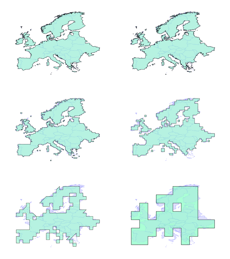
  • Snap-rounding allows full support for specifying the output precision model.  The precision model can be specified independently for each overlay call, which is more flexible and easier to use.  The use of snap-rounding also provides fully valid precision reduction for geometries.  This makes it feasible for the first time to fully operate in a fixed-precision regime.
Precision Reduction turned all the way up to 11
  • Significant performance optimizations are included (notably, one which makes polygon intersection much faster in many cases)
Intersection of a MultiPolygon with a grid (7x faster with OverlayNG)
  • Pluggable noding allows providing different noding strategies.  One use is to run OverlayNG with the original floating-point noder, which is faster than snap-rounding (but of course has the robustness issues noted above).  Another is to use a special-purpose noder to provide very fast polygonal coverage union.
Union of a polygonal coverage (10x faster with OverlayNG)
  • modular and cleaner codebase allows easier testability, maintenance, enhancement and reuse.  A winged-edge graph model is used for the topology graph. This is simpler and less memory intensive.
  • The rebuild gives an opportunity to make some semantic improvements: 
    • Empty results are returned as empty atomic geometries of appropriate type, rather than awkward-to-handle empty GeometryCollections
    • Linear output is merged node-to-node.  This gives union a more natural and useful  semantic
A benefit of the new codebase is that it is easier to enhance and extend.  For example, it should be straightforward to finally provide a SplitPolygon function for JTS.  Another potential extension is overlay for Polygonal Coverages.

Code that is so widely used needs to be thoroughly tested against real-world workloads.  Initially OverlayNG will be released as a separate API in JTS.  This allows it to be used along with the original overlay.  It can be used as a fallback for cases which fail in the original overlay process.  Once the new code has been proved out in real world use, it is likely to become the standard overlay code path. Also, the code will be ported to GEOS soon, where we're hoping it will provide significant benefits to the many systems that use GEOS.

I'll be posting more articles about aspects of OverlayNG soon. The code is almost ready to release, after some final testing. In the meantime, the pre-release code is available in a Git branch. It would be great to get as much beta-testing as possible before final release, so try it out and log some feedback!


Tuesday, 14 April 2020

Maximum Inscribed Circle and Largest Empty Circle in JTS

There is often a need to find a point which is guaranteed to lie in the interior of a polygon.  Uses include placing cartographic labels, and using the point as a proxy for polygon containment or overlap (such as in polygon overlay).

There are several ways to compute a "centre point" for a polygon.  The simplest is the polygon centroid, which is the Center of Mass of the polygon area.  This has a straightforward O(N) algorithm, but it has the significant downside of not always lying inside the polygon!  (For instance, the centroid of a "U" shape lies outside the shape).  This makes it non-useful as an interior point algorithm.

JTS provides the InteriorPoint algorithm, which is guaranteed to return a point in the interior of a polygon.  This works as follows:
  • Determine a horizontal scan line on which the interior point will be located. To increase the chance of the scan line having non-zero-width intersection with the polygon the scan line Y ordinate is chosen to be near the centre of the polygon's Y extent but distinct from all of vertex Y ordinates.
  • Compute the sections of the scan line which lie in the interior of the polygon.
  • Choose the widest interior section and take its midpoint as the interior point.
This works perfectly for finding proxy points, and usually produces reasonable results as a label point.  

However, there are polygons for which the above algorithm finds points which lie too close to the boundary for a label point.  A better choice would be the point that lies farthest from the edges of the polygon.  The geometric term for this construction is the Maximum Inscribed Circle. The farthest point is the center of the circle. 

Comparison of center points for a not-so-typical polygon

In the geographic domain this is romantically termed the Pole of Inaccessibility.  
Pole Of Inaccessibility in Canada

This point occurs at a node of the medial axis of the polygon, so in theory all that is needed is to compute the medial axis and test the set of node points.  However, medial axis algorithms are notoriously difficult to implement, and can be expensive to compute.  So it's appealing to look for a simple and fast way to compute a good approximation to the Maximum Inner Circle center.  There have been various approaches to this, including a geodetic grid-based approach by Garcia-Castellanos & Lombardo, and one by Martinez using random point distributions.  Recently Mapbox released a clever implementation which uses successive refinement of a grid along with a branch-and-bound technique to reduce the amount of searching needed.  

JTS now has a version of this algorithm, called MaximumInscribedCircle.  It significantly improves performance by using spatial indexing techniques for both polygon interior testing and distance computation.  This makes it very fast to find the MIC even for large, complex polygons.  Performance is key for computing label points, since it is likely to be used for many polygons on a typical map.

Grid refinement to find Maximum Inscribed Circle

An interesting property of the MIC is that its radius is the distance at which the negative buffer of the polygon disappears (becomes empty).  Thus the MIC radius length is a measure of the "narrowness" of a polygon.   This is often useful for purposes of simplification or data cleaning, to remove narrow polygonal artifacts in data.

Sequence of negative buffers containing the Maximum Inscribed Circle center

And, as the infomercials say, that's not all!  If you act today you also get a free implementation of  the Largest Empty Circle !  The Largest Empty Circle is defined for a set of geometric obstacles.  It is the largest circle that can be constructed whose interior does not intersect any obstacle and whose center lies in the convex hull of the obstacles.  The obstacles can be points, lines or polygons (although only the first two are currently implemented in JTS).  Classic use cases for the Largest Empty Circle are in logistics to find a location for a new chain store in a set of store locations; or to find the largest roadless area in environmental planning.

It turns out that the LEC can be computed by essentially the same algorithm as the MIC, with a few small changes.  And of course it also uses spatial indexing to provide excellent performance.
Largest Empty Circles for point and line obstacles


Maximum Inscribed Circle and Largest Empty Circle are now in JTS master, and will be released in the upcoming version 1.17.

Further Improvements

There are some useful enhancements that can be made:
  • For Maximum Inscribed Circle, allow a second polygonal constraint.  This supports finding a label point within a view window rectangle.
  • For Largest Empty Circle, allow a client-defined boundary polygon.  This allows restricting the circle to lie within a tighter bound than the convex hull
  • For both algorithms, it should be feasible to automatically determine a termination tolerance


Monday, 3 February 2020

Running commands in the JTS TestBuilder

The JTS TestBuilder is a great tool for creating geometry, processing it with JTS spatial functions, and visualizing the results.  It has powerful capabilities for inspecting the fine details of geometry (such as the Reveal Topology mode).  I've often thought it would be handy if there was a similar tool for PostGIS.  Of course QGIS excels at visualizing the results of PostGIS queries.  But it doesn't offer the same simplicity for creating geometry and passing it into PostGIS functions.

This is the motivation behind a recent enhancement to the TestBuilder to allow running external (system) commands that return geometry output.  The output can be in any text format that TestBuilder recognizes (currently WKT, WKB and GeoJSON).   It also provides the ability to encode the A and B TestBuilder input geometries as literal WKT or WKB values in the command.  The net result is the ability to run external geometry functions just as if they were functions built into the TestBuilder.

Examples

Running PostGIS spatial functions

Combined with the versatile Postgres command-line interface psql, this allows running a SQL statement and loading the output as geometry. Here's an example of running a PostGIS spatial function.  In this case a MultiPoint geometry has been digitized in the TestBuilder, and processed by the ST_VoronoiPolygons function.  The SQL output geometry is displayed as the TestBuilder result.

The command run is:

/Applications/Postgres.app/Contents/Versions/latest/bin/psql -qtA -c 
"SELECT ST_VoronoiPolygons('#a#'::geometry);"

Things to note:
  • the full path to psql is needed because the TestBuilder processes the command using a plain sh shell.  (It might be possible to improve this.)
  • The psql options -qtA  suppress messages, table headers, and column alignment, so that only the plain WKB of the result is output
  • The variable #a# has the WKT of the A input geometry substituted when the command is run.  This is converted into a PostGIS geometry via the ::geometry cast.  (#awkb# can be used to supply WKB, if full numeric precision is needed)

Loading data from PostGIS

This also makes it easy to load data from PostGIS to make use of TestBuilder geometry analysis and visualization capabilities.  The query can be any kind of SELECT statement, which makes it easy to control what data is loaded.  For large datasets it can be useful to draw an Area of Interest in the TestBuilder and use that as a spatial filter for the query.  The TestBuilder is able to load multiple textual geometries, so there is not need to collect the query result into a single geometry.


Loading data from the Web

Another use for commands is to load data from the Web, by using curl to retrieve a dataset.  Many web spatial datasets are available in GeoJSON, which loads fine into the TestBuilder. Here's an example of loading a dataset provided by an OGC Features service (pygeoapi):


Command Panel User Interface


The Command panel provides a simple UI to make it easier to work with commands.  Command text  can be pasted and cleared.  A history of commands run is recorded for the TestBuilder session.  Recorded commands in the session can be recalled via the Previous and Next Command buttons.
Buttons are provided to insert substitution variable text.


To help debug incorrect command syntax, error output from commands is displayed.


It can happen that a command executes successfully, but returns output that cannot be parsed.  This is indicated by an error in the Result panel.  A common cause of this is that the command produces logging output as well as the actual geometry text, which interferes with parsing.  To aid in debugging this situation the command window shows the first few hundred characters of command output.  The good news is that many commands offer a "quiet mode" to provide data-only output.

Unparseable psql output due to presence of column headers.  The pqsl -t option fixes this.


If you find an interesting use for the TestBuilder Command capability, post it in the comments!